Route setting
Each board contains a 16-position switch for configuring the multiplexers that direct the JTAG either around the board, or out over the external connections. The multiplexer selection is encoded with a 4-bit value, where the bits representing Top, Right, Bottom and Left are encoded as 0bLBRT. A bit set to '1' routes the JTAG within the board; a '0' out over the link in that particular direction. So for example, the position '5' (0b0101) would assume the JTAG chain moves through the left and right of the board, but not up or down. The edge to which the XTAG connector should also have its bit set to 0.
In a grid, imagining several boards laid flat, the XTAG must be plugged into the top-left board, move along the top row, then down to the next row and along that, and continuing as shown in the diagram further down this page.
JTAG IDs
The processor node IDs seen over JTAG from an XTAG-2 connected to a Swallow board differ from the node IDs that are seen by software running over them.
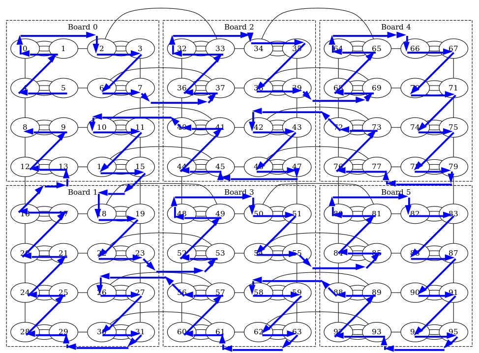
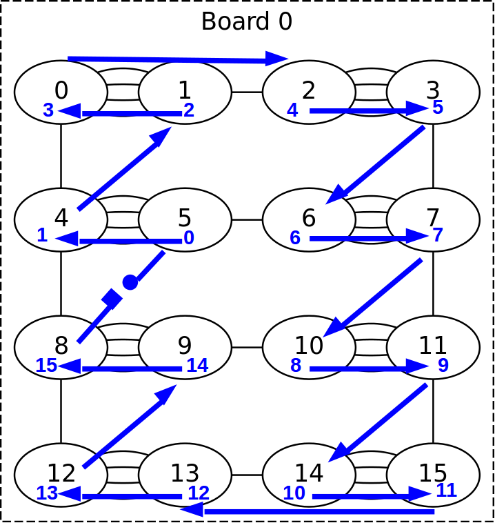
In the following diagrams, the blue arcs show the JTAG chain and numbers show the core ID as shown by gdb stdcore[].
In black are the node ids as seen by software, which is equal to what a call to get_core_id() returns.
Single board
6 boards, arranged 3h x 2w