XMOS tools vs Swallow tools
There are two separate tool chains that are compatible with Swallow:
- The vanilla XMOS XTimeComposer tools
- The custom Swallow tool chain
XMOS tools
The standard XMOS tools are capable of compiling, debugging and analysing multi-core programs and they can be used with Swallow boards.
However, there are several major drawbacks to using the tool chain, including:
- A hard-coded limit of ~100 processors, limiting us to a maximum of 6 Swallow slices
- Compile times in the order of minutes for even a single board.
- All debug via JTAG, which has a massive slowdown effect on the system.
- They cannot support non-rectangular topologies.
For these reasons, we have created a custom tool-chain, the Swallow tools.
Swallow tools
Link to Tool Download Instructions
The Swallow tools are based on the XMOS tool chain, but re-implement the compilation front end, linking and output to a custom "multi-core binary" format.
The key differences in using the tools are:
- They are command-line only
- The
mainfunction must be declared in a separate file to the remainder of the code (any number of source files are supported). - The main file must contain the line
#define MCMAIN
The various tools are discussed later in this page, but the output is a single .sgb (Swallow Grid Binary) file, which can be immediately downloaded to the Swallow system.
Programming and tracing
Quick start instructions to program Swallow
Overview
The Swallow tools program Swallow systems over Ethernet. Debug output also comes over ethernet. Ethernet can also be used to stream in and stream out run-time data. The conventional JTAG connection is not required, except for the connection of a global reset signal.
Swallow slices do not have built-in Ethernet support, so Ethernet connectivity is provided by the addition of a peripheral "Etherboot" board.
Etherboot
Etherboot hardware
The Etherboot board connects to the Swallow network. It is always added to the S2 connection of the bottom-right Swallow slice (when their topology is visualised as a 2D grid).
The top-left connector (P3) is used.
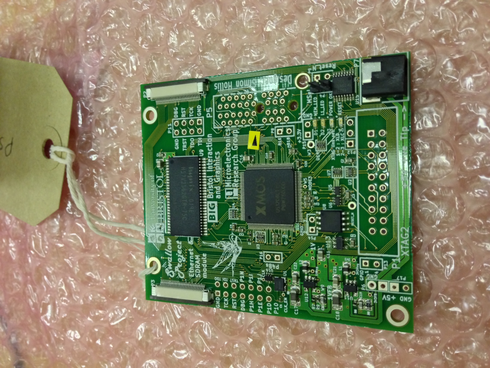
A global reset connection must also be added to the Swallow boards to allow the Etherboot module to reset before programming. To do this, a single wire must be connected between pin GPIO1 (top pin of P13) on the Etherboot board and pin 15 of the XTAG2 header on the top-left most Swallow slice in the array (pin 15 is the 8th pin up from the arrow marked '1' on P5).
An XTAG2 is connected to the Etherboot module to allow programming and I/O, and an ethernet XSlice is added to the PCIe header on the Etherboot board.
An ethernet cable is then connected to a host PC, as well as the USB connection of the XTAG2.
Etherboot software
The Etherboot slice runs a standard single-core XE binary, using the standard XMOS toolchain. The resulting binary is etherboot.xe and need only be compiled once for each Swallow topology.
The etherboot code is available on github: git@github.com:stevekerrison/sw_swallow_etherboot.git
There is a Makefile included, but *before Making etherboot.xe, one needs to set the board configuration in:
sw_swallow_etherboot/app_swallow_etherboot/src/swallow_etherboot_conf.h*
Calculating NodeIDs
Node IDs are encoded like this:
Row: Most extreme North is row 0, then proceeds south with +1 per row
Column: Most extreme West is column 0, then proceeds East with +4 per column
Bit | 15 | 14-8 | 7 - 2 | 1 | 0
Purpose | Is Xscope | Row | Col | Layer | Is Peripheral
swallow_id() will take a core index (e.g. 5) and turn it into a node ID appropriate for the grid you're running on (yes, it's a runtime thing).
Similarly, swallow_cvt_chanend() is used by the mcsc script to generate channel addresses then convert the top 16-bits into the real node ID.
These are found in sc_swallow_communication; you will find some stuff in ledtest.xc in tool_xmp16_manycore/code that uses them. You can also look at swallow-mcsc.py and see how the code it generates uses them.
SDRAM addition
ID: ID of connected node | 1
Program it seperately and give it this id.
.xn file in the etherboot code "Swallow-Ethernet-v2" code: the .xn file contains "RoutingId=NNNN". This is the node ID.
N.B. In order to get the network generated, this .xn file must include the XSCOPE entry of connected core ID, as shown in the example .xn
- Steve needs to supply code for bringing up link on Swallow and link on peripheral board and program peripheral routing tables.
-> Ask for credit. Get it. Tell to ask for credit. Ask. Get.
Helper functions
swallow_cvt_chanend()
Take a chanend which assumes a physical index on the row/column indexing scheme and convert it to the real chanend.